Luminaire Define - Photometry Section
The Lumens Per Lamp field is used for "Relative luminaire photometry" which is typical of HID, fluorescent and incandescent sources. LED sources are tested using "Absolute luminaire photometry" where there is no "lamp" and the lumens in this cell are expressed as a negative one (-1) per IES document LM-63-18. LED lumen output is calculated from zonal lumen values and will be shown in the Luminaire Lumens field. The following discussion is provided with respect to what are today considered mostly legacy sources using relative photometry.
When a luminaire has been selected, the Lumens Per Lamp value that appears in the Define Luminaire dialog is extracted from the photometric file and is the basis for the photometric report. Should this test lamp lumen value not be the desired one, it can be changed by simply clicking the mouse in the Lumens Per Lamp cell and changing the lumens, unless it is an absolute test with a negative 1 in the field (when opening a file based on absolute photometry you cannot change the lumen figure from the reported negative one (-1).
Lumen proration is necessary when simulating performance of a lamp type different than the test lamp, or when using a photometric file that is based upon a derated value such as 1000 lumens. For example, it is often necessary to prorate the lumen output to represent a lamp of different wattage or variety. AGi32 allows you to insert virtually any value for the lamp's lumen output, although it is recommended that the manufacturer be consulted with regard to the accuracy of the proration. In the case of luminaire photometry reported per 1000 lumens, the figure of 1000 will appear in the Lumens Per Lamp cell. Simply change this to the rated lamp lumens.
Generally, the lumen figure refers to a single lamp's lumen rating. Luminaires containing multiple lamps will be treated appropriately, provided the photometric format is followed. Luminaires containing multiple lamps of different varieties, such as metal halide and high-pressure sodium, will use a lumen value that averages the single lamp lumens of every lamp contained within the luminaire.
Regarding LER and LCS and BUG ratings:
- The calculated LCS and BUG metrics are automatically updated to reflect any changes to the Lumens Per Lamp value in the luminaire definition when the definition is Added or Redefined. When you initially change the lumen value, the LCS data and graph will indicate ‘Pending – Lumens have been changed’. The data will be updated and displayed as soon as the definition is updated. This feature allows you to generate accurate LCS data and BUG ratings for luminaires with prorated lamp lumen values.
- The calculated LER metric is automatically updated to reflect any changes to the Lumens and/or Watts values in the definition when the definition is committed. When you initially change the watts value, the Classification will display ‘Pending – Watts have been changed’. The data will be updated and displayed as soon as the definition is updated.
- Important: LCS, BUG and LER metrics displayed in the Instabase are based on the test report lumen and watts values. Prorating the lumen and/or watts values in the luminaire definition will result in different LCS, BUG and /or LER metrics in the Luminaire Definition dialog than what is shown in the Instabase dialog.
Linking to Photometric Toolbox from within the Luminaire Define dialog will include the lumen and watts values specified in the luminaire definition (not the original test data) to ensure that all generated reports in Photometric Toolbox are based on these modified values.
This value is typically used for legacy sources such as fluorescent, HID or incandescent. It is not editable when using LED test reports with a negative one (-1) in the Lumens per Lamp field. Using legacy sources you can change the number of lamps to prorate luminaire output.
The Luminaire Lumens is a measure of luminous flux emitted by the luminaire. For LED sources this will be the total zonal lumen output (lumens in all zones). For legacy sources tested using relative photometry this is the total lamp lumens multiplied by the decimal efficiency (also the total zonal lumen output).
Efficiency (%)
Luminaire Efficiency is the ratio of Luminaire Lumens to Total Lamp Lumens (number of lamps x lumens per lamp). If the calculated Efficiency is greater than 100%, a warning message is displayed indicating that there is a potential problem with the file. The luminaire manufacturer or supplier should be contacted for a corrected file.
As with lamp lumens, the luminaire test watts are also extracted from the photometric file. We recommend verifying that this value is accurate, as this is the value used to calculate Lighting Power Density. Typically, this figure should reflect the total connected load or combination of source and electronic or ballast watts. As with lamp lumens, this value can be changed to represent luminaires of different wattage and variety.
Regarding LER, LCS and BUG ratings:
- The calculated LER metric is automatically updated to reflect any changes to the Lumens and/or Luminaire Watts values in the definition when the definition is Added or Redefined. When you initially change the watts value, the Classification will display ‘Pending – Luminaire Watts have been changed’. The data will be updated and displayed as soon as you update the definition.
- Important: LCS, BUG and LER metrics displayed in the Instabase are based on the test report lumen and luminaire watts values. Prorating the lumen and/or luminaire watts values in the luminaire definition will result in different LCS, BUG and /or LER metrics in the Luminaire Definition dialog than what is shown in the Instabase dialog!
Linking to Photometric Toolbox from within the Luminaire Define dialog will include the watts values specified in the luminaire definition (not the original test data) to ensure that all generated reports in Photometric Toolbox are based on these modified values (this has changed from previous versions).
S/P Ratio is the ratio of source Scotopic luminous flux to Photopic luminous flux. It is used to rank the effectiveness (for visual performance) of light sources and is derived from the source Spectral Power Distribution data. The source S/P Ratio is required for calculation of Mesopic luminance and/or illuminance.
Some representative S/P Ratios of various sources can be found in IES document TM-12-12. S/P Ratios for a specific lamp type may also be obtained from the lamp manufacturer.
See Photopic, Mesopic, Scotopic - Concepts for additional information.
The Light Loss Factor is a multiplier used to simulate a reduction in lumen output due to factors such as dirt depreciation, lumen depreciation over time, ballast factor and others. The factors are multiplied together to achieve the total light loss factor (Total LLF). In its simplest form, the light loss factor is composed of many components, which will vary with any given project. For more information please refer to the IES Lighting Library.
Specify Button - The optional Specify Button provides a convenient way to sum the various most common factors that compose the Total LLF. You can use any or all of the factors by entering decimal data in the cells provided.
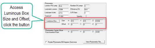
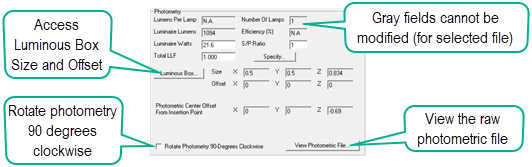
The physical size of a luminaire's luminous area is obtained from the photometric file. AGi32 uses this information to create a rectangular shape we call the Luminous Box. The luminous box may have a luminous Z-dimension for some luminaires, for others it is almost two-dimensional. The X-dimension corresponds to the distance across the luminous opening along the 0-180 photometric plane. The Y-dimension corresponds to the distance across the luminous opening along the 90-270 photometric plane.
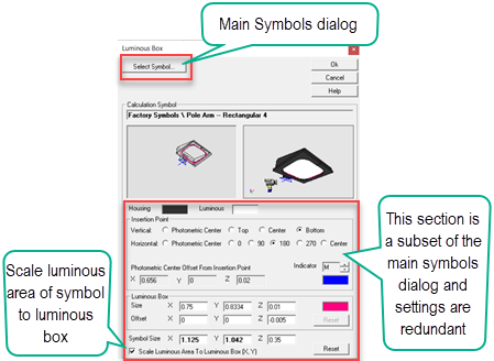
Using Smart Symbols the luminous area of the selected symbol is automatically scaled to match the size of the luminous box. This scales the symbol accurately for a reasonable approximation of an actual luminaire in size. You may scale the Z-dimension of the symbol independently to your liking. The relationship between the symbol's luminous area and the luminous box can be broken by deselecting the check box in the Symbols dialog (shown below). The Small version of the Symbols dialog (below) can be opened by clicking the Luminous Box button (shown above) in the Photometry Section of the Define dialog.
The dimensions of the luminous box are used when performing lighting calculations using the Full Radiosity Method. With the Direct Only Method, the luminaire is assumed to be a point source. If the luminous dimensions found in the photometric file are incorrect, the lighting calculations may not be accurate. For example, if the distribution of a linear luminaire is emitted from a point source instead of an appropriately sized luminous area, the luminous area will not be discretized appropriately. The effect is most noticeable when the luminaire is placed close to a surface. Care should also be taken that the luminous box does not extend outside of the room and is not penetrating any objects. For recessed luminaires, the luminous area should be below the ceiling. AGi32 automatically assigns a slight negative Offset parameter to ensure this is the case for luminaires with no luminous height.
The Luminous Box is associated with the luminous area of the Calculation symbol by default (when the Scale Luminous Area... check box is enabled). Specifically, the Z=0 portion of the luminous box is aligned with the center of the luminous area of the Render symbol. This association may place the luminous box at some distance away from the insertion point of the luminaire (mounting height). As an extreme example, if the Shoebox-Yoke symbol is selected, the luminous area is located 1 foot above the insertion point of the luminaire. If a 15 foot mounting height is specified, the calculations will actually consider the luminous source at 16 feet above grade.
Note: Please see the IESNA document, LM-63, for more information about the luminous dimensions given in IES format photometric files.
Rotate Photometry 90 Degrees Clockwise (check box)
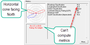
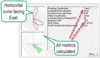
When opening some photometric files tested in Europe, the zero degree horizontal plane (called C0) may be facing North or parallel to an imaginary curb line. This is often seen with roadway-specific luminaires. In North America (and many other locales), the IES standard places C0 perpendicular to the curb, facing into the road. It would then appear to point East. AGi32 provides a convenient method to normalize the European test method to IES standards with a check box titled "Rotate photometry 90 degrees clockwise". Apply this check box and the report will now function as expected within AGi32 and in accordance with all calculated metrics. More information.
|
|
| BEFORE Rotate 90 Degrees Clockwise | AFTER Rotate 90 Degrees Clockwise |
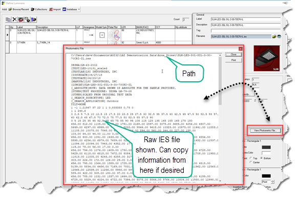
It is possible to look at the raw photometric file data using the View Photometric File button. This opens a text window where you can copy information if you like (you cannot paste). This function is most helpful for seasoned professionals who understand the raw format data. The filename and path are shown across the top of the window.